2025 - 2026 | Formula SAE Electric
SN5 is our latest car for the 2026 competition. Taking the simulation workflows I started over the previous design cycle, I integrated them with cross-subteam collaboration to design the steel spaceframe. In addition, a big part of this year has been getting exposure to validation and testing using equipment including Creaform Scanners, Instron Universal Testers, and composites manufacturing for a composite AIP slated for SN6.
ROLE
Mechanical Engineer
TOOLS


Summary
The design process for SN5 starts from judge feedback at competition.
Goals are set top down, spanning L1 to L3. L1 targets are set by the sims team, which projects laptime and complience specs using VD software. L2 are broader project goals and L3 are the specific engineering goals in order to achieve the broader ones. All design decisions are made with an emphasis on these.
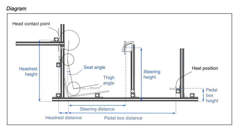
Vision & Ergo Study
In order to understand the needs of the driver, especially in relation to Front Hoop sizing and wheel visibility, we conducted a vision study to quantify the amount of sightline change for various geometries. Working with our drivers, I was able to understand the important factors from chassis that impact driver performance as well as gathering quantifyable numbers to know what to stay within.
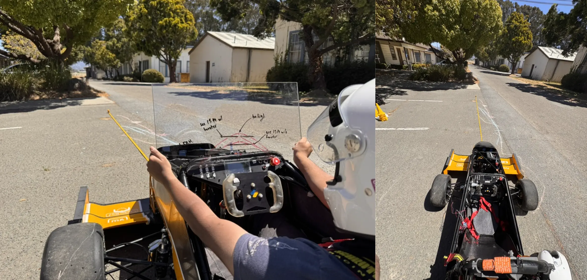
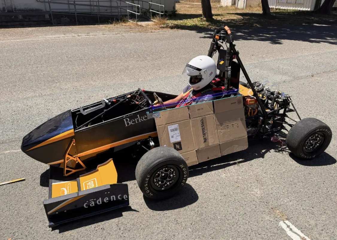
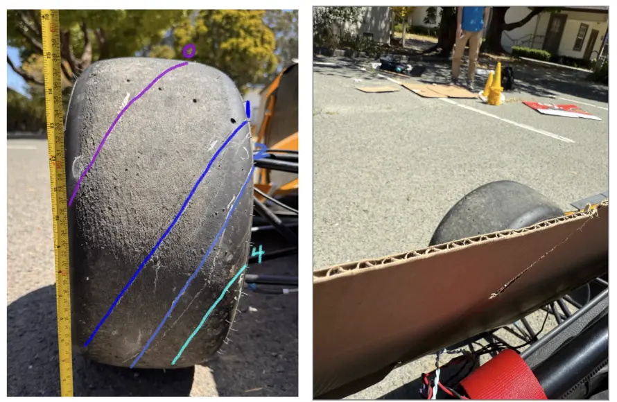
For all dimensions related to driver comfort and placement for brakes, steering, seating, firewall, headrest, and elbow room, an ergo jig was constructed using 8020 hardware and lasercut wood pieces. Per rules, the car has to accomodate both sizes ranging from 5th percentile female as well as 95th percentile male. In order to achieve this, data was collected across a variety of members of the team. For this study, I assisted in manufacturing, assembly, and data collection alongside our amazing brakes/ergo subteam.
Tube Sizing & Calculations
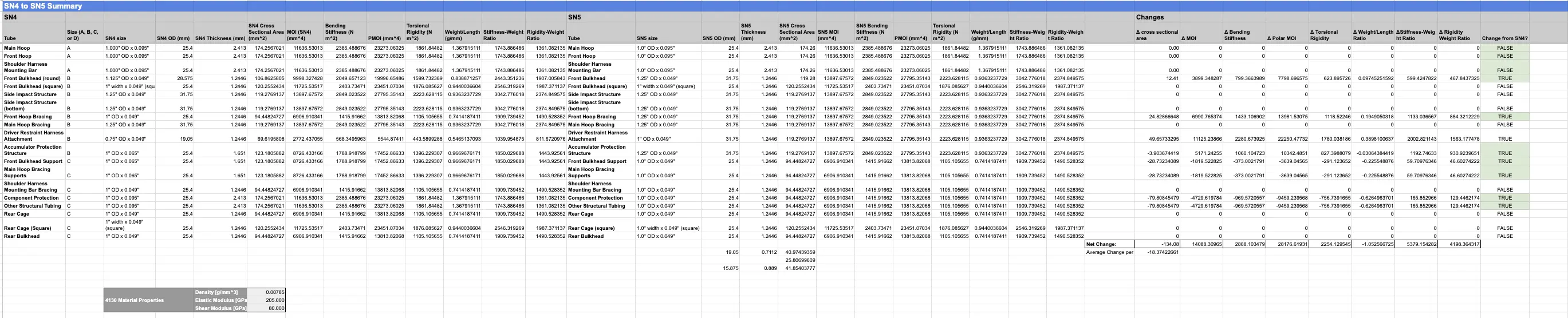
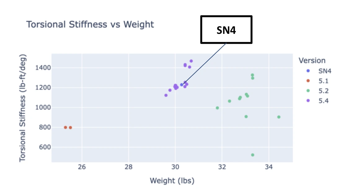
The Rules specify minimum inertias and thicknesses for some sizes of tubes, with many left unregulated if not particularily structurally important. Using first principles justifications, we applied statics to create a sizing calculation spreadsheet for easy comparison as well as use Method of Deflections for a preliminary hand-calc to understand stress distribution for SN4.
Using this spreadsheet, we're able to identify the changes from SN4 to SN5 for changes in area, weight, inertia, and stiffness. A key improvement for this year was going for thinner tubes down to 0.028" for non-structural applications given welder experience and training. Justification for those application areas can be found below.
Interactive Tube Selection Chart
To streamline the selection process and ensure rule compliance across all FSAE tube sizes, I developed a custom interactive D3.js visualization. This tool maps out the entire catalog of available 4130N steel tubes, filtering them by shape, wall thickness, and mass to instantly identify which options meet the strict Area and Area Moment of Inertia (MOI) requirements.
The tube calculation was actually an extension of a class project from the Mechanics of Materials course, using the Direct Stiffness Method to calculate chassis tube deflections. This involved deriving local element stiffness matrices based on material properties (E, G) and cross-sectional geometry (A, I, J), applying coordinate transformations for 3D space, and assembling a global stiffness matrix to solve for nodal displacements under load.
I'm excited for future more advanced classes to take this simplified model (pin-pins, node specific, etc.) to a more realistic one that could validate our FEA findings. However, it was still a great experience transforming a course project to an FSAE application.
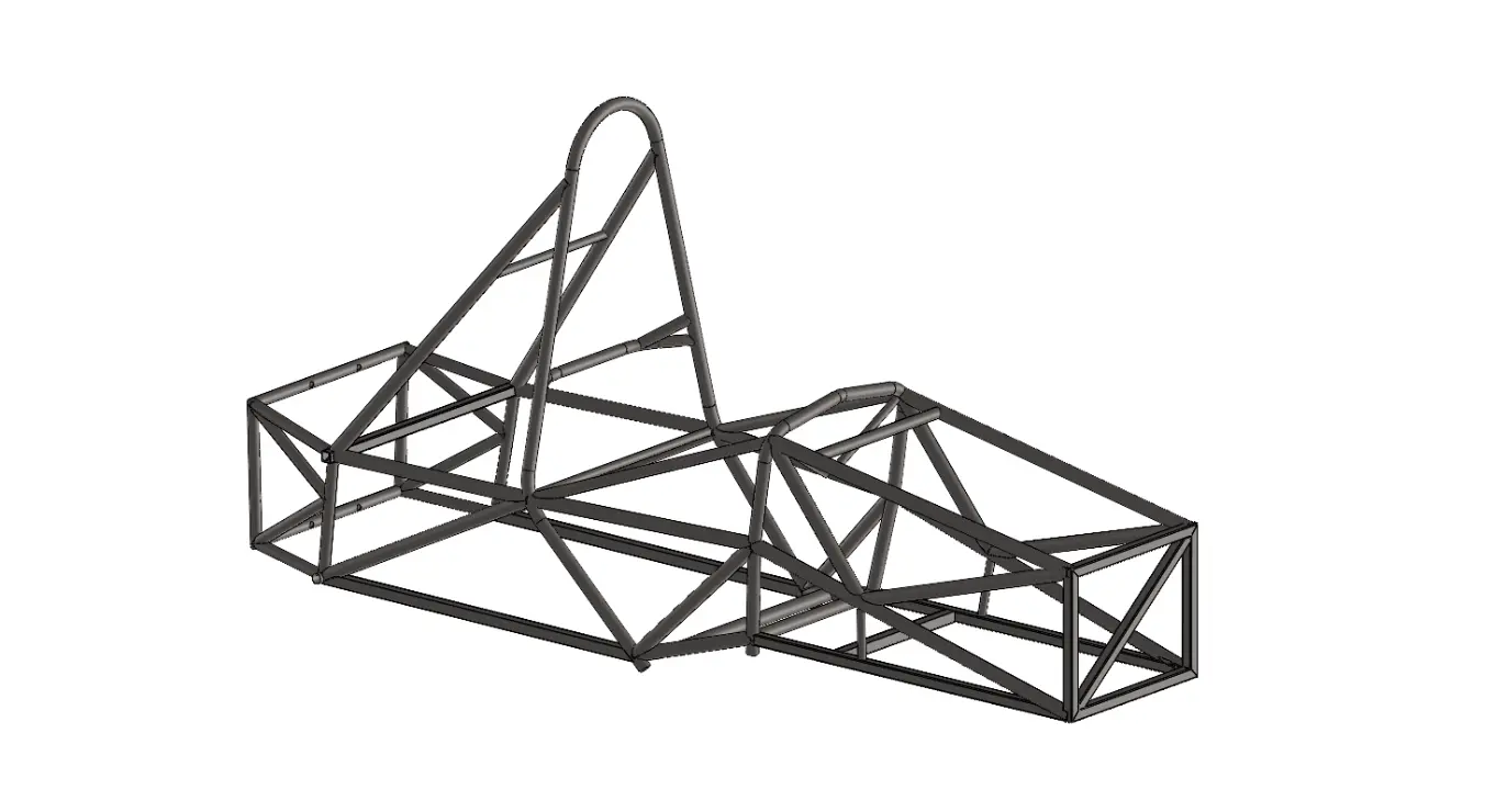
Master Sketch
Now that we're ready to start CAD and design, the chassis subteam sets the master 2D sketches that will dictate spaceclaim and key dimensions. Working as the mediators between all other subteams, the master sketch ensures rule compatibility as well as the overarching blueprint for other engineers to derive their cad off.
Design
Using an iterative process, I played around with many unique geometries with a goal of increasing stiffness-to-weight and improving packaging for other subteams. This included:
- Subteam Request: Ensuring everyone gets what they need for their respective components
- Rear Packaging: Tapered & roll hoop designs
- Steering Tubes: Angled, single, and braced designs.
- Cockpit Area: Rounded and triangulated sides versus triangle downwards.
- Unregulated Tubing: Stiffness-specific tubes between wheelbase.
Simulation
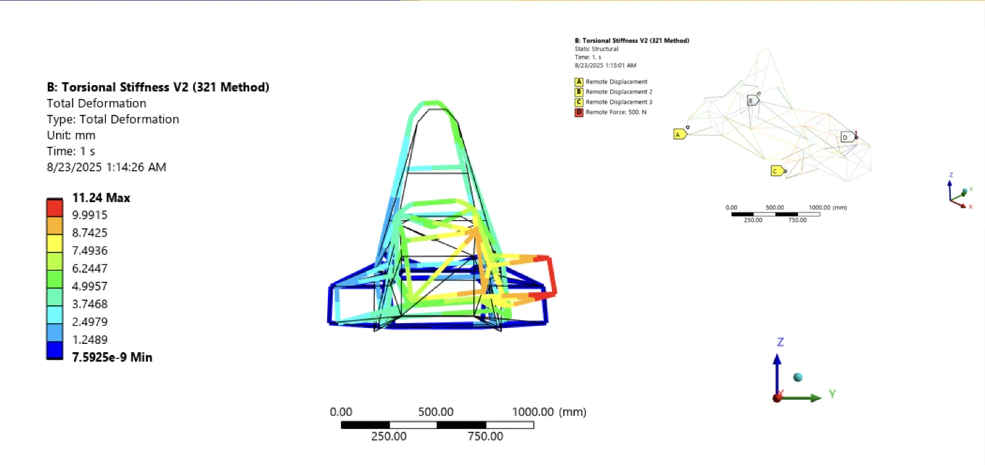
Complex 3-2-1 Rigid Body Method
This setup simulates the entire vehicle assembly to capture realistic suspension interactions.
- Constraints:
- Back Right: Fixed all translation.
- Back Left: Fixed X and Z translation.
- Front Right: Fixed Y translation.
- Forces: Upward force applied to the left tire contact patch.
Simplified Method
This method isolates the chassis to speed up iteration time while maintaining accuracy.
- Constraints: Rear wheels orthogonally anchored, allowing free twist about the longitudinal axis.
- Left Rear: Fixed Y and Z translation, fixed Y rotation.
- Right Rear: Fixed X and Z translation, fixed X rotation.
- Forces: Downward force on left damper attachment; Upward force on right damper attachment.
Evolution: SN4 vs. SN5
SN4 (Previous)
Ratio: ~41 Nm/deg/kg
SN5 (Current)
Ratio: 53.6 Nm/deg/kg
+30% Stiffness-Weight Ratio Increase
Ultimately, torsional stiffness goes back to complience, which using the equations and calculations I set up during SN4's development, we're able to quantify how much factors such as tunability, understeer gradient, and LLTD-RSD tradeoffs stem from the chassis's flexibility.
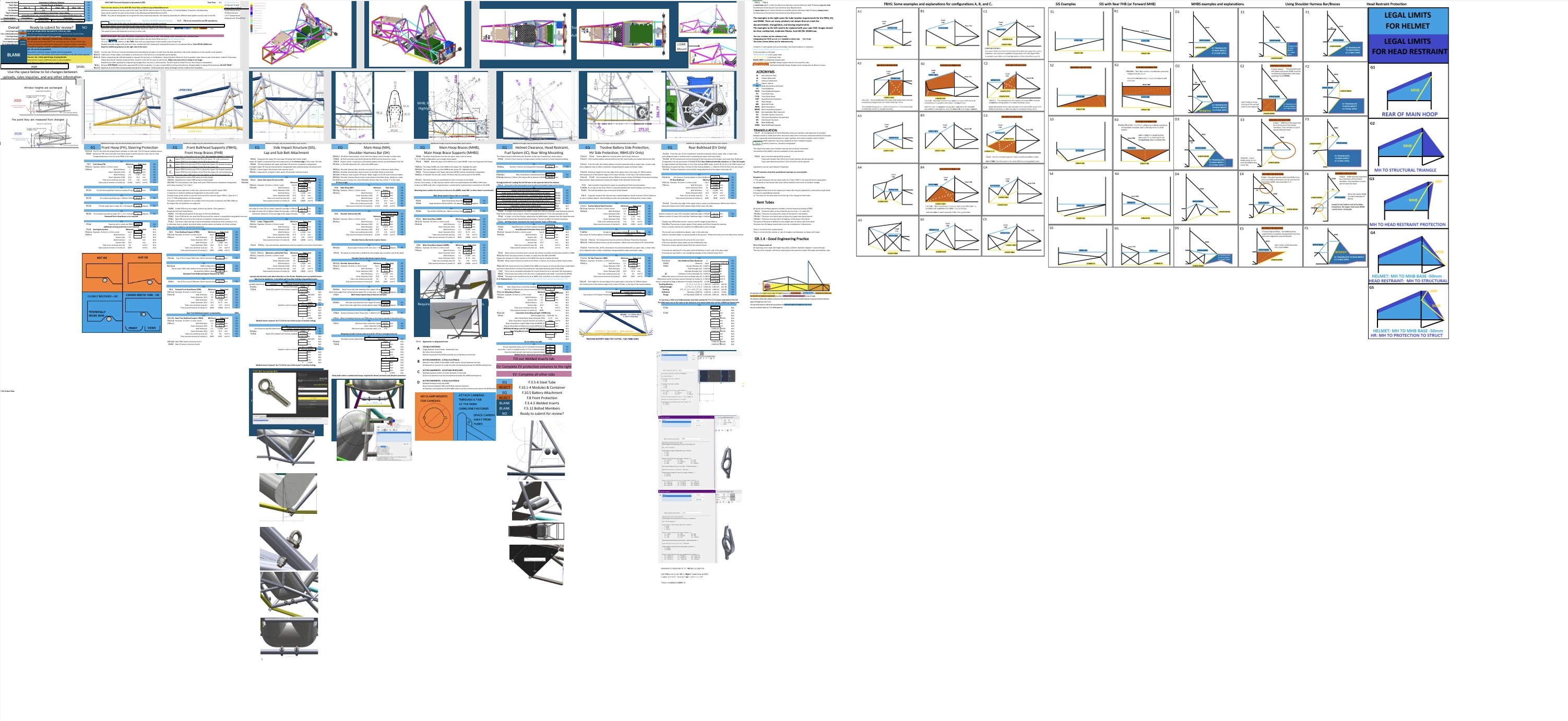
SES Submission
A critical milestone in the design cycle is the submission of the Structural Equivalency Spreadsheet (SES), which serves as the official proof that the chassis meets all FSAE safety regulations.
Design Reviews
Project Roadmap
Phase 1: Design
Complete
Phase 2: Manufacturing
In Progress
Phase 3: Testing
Coming Spring 2026
Manufacturing & Testing Updates Coming Soon!